Overview
» get the Agent » PSsystec Downloads
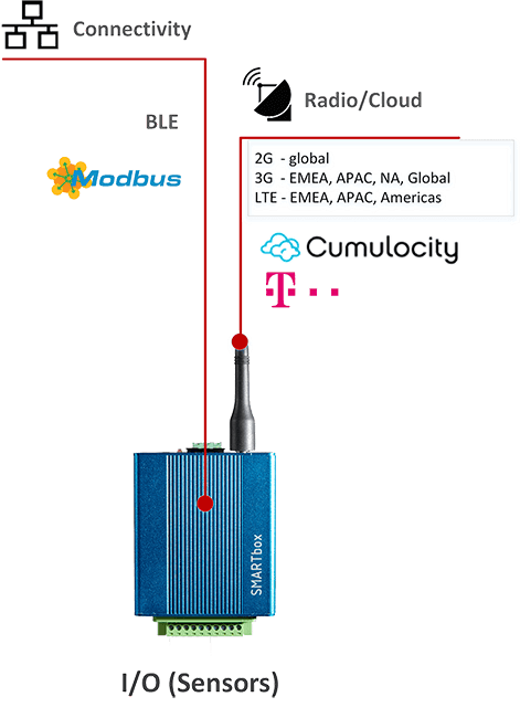
Smartbox, based on the Telit Chipset xE910 is a ready to use solution for connecting BLE Devices to the Cumulocity/Cloud of Things IoT Cloud. The SMARTbox acts as a client collecting data from up to 8 BLE devices. Easy connect and configure the used BLE devices in the cloud by Cloud fieldbus. Using the MQTT protocol the terminal comes up with a low traffic solution.
Datasheet
Radio
| Radio | |
|---|---|
| 4G LTE | |
| 3G | |
| 2G | GSM | GPRS |
| Regions | EMEA / APAC / Latinamerica / NorthAmerica / Australia / Global (3G / 2G) |
| GPS | Supported by 2G and 3G Variances |
| Production | The selected Region,Technology and GPS can be defined during Production. The default assembly is 3G with supported regions EMEA / APAC |
Connectivity/ Features
| Connectivity/ Features | ||||
|---|---|---|---|---|
| Layout | 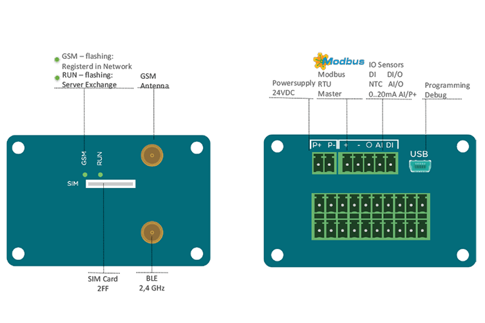 |
|||
| BLE | Qualification | v5.0 (Bluetooth low energy) | ||
| Type | GATT Client | |||
| Connectivity | 1-8 Nordic Thingy52 BLE sensors (Automatic Custom service identification of generic BLE sensors – not released yet) | |||
| Chip | NINA-B111-02B (ublox) | |||
Fieldbus Modbus  |
Type | Modbus RTU Master | ||
| Baudrate | 4800, 9600, 19200, 38400, 57600, 115200 | |||
| Parity | Even, ODD, NONE | |||
| Stoppbits | 2,1 | |||
| Functioncodes | ||||
| Datapoints | Max. 10 Modbus Slaves, with 100 datapoints per device or 1000 datapoints with 1 device | |||
| Sensors | Number | 12 | ||
| U1/U2/U3/U4/U5/U6/U7 | DIN NO [High Side] 24VDC | |||
| U8 | 0..20mA | |||
| U9/U10 | DO – Digital Output 24VDC | |||
| Output | 24VDC Digital Output. Note: Either the Output or the 2nd Fieldbusinterface can be selected during production | |||
| DIN/O | DIN [voltage free] (defined by Hardwarejumper) | |||
| AIN/O | NTC (selectable by Hardwarejumper, either NTC or 0..20mA) | |||
| AIN/P+ | 0…20mA (selectable by Hardwarejumper, either NTC or 0..20mA) | |||
| LEDs | GSM | Flashing- connected to mobile network | ||
| RUN | 2xflashing/pause: StartUp Phase 3xflashing/pause: Connected to Server, Data exchange | |||
| Act | Flashing: Sensor Board Power | |||
| Link | Flashing: Sensor Board is ready to process data | |||
| USB | For programming, Logging and Trace the device | |||
Cloud Connector
| Cloud Connector | ||||
|---|---|---|---|---|
| Availability | All Cumulocity Based systems, Cloud der Dinge, Deutsche Telekom | |||
| Realtime Clock | Updating Realtime automatical from #NTP timeserver | |||
| Application | CloudFieldbus (CFB Integrated in Devicemanagement)For SetUp connected field devices | |||
| Online Operations | Remote Restart Fieldbus Configuration Cloud-Device Change Transmitinterval from device to Cloud Change Communication. Baudrate, Databits, Parity, Stopbits Operate the connected Field device: Registervalues (R/W) Operate the connected Field device: Change CoilValues (R/W) Operate the device with AT Commands in the shell | |||
| Communication | MQTT | |||
| Security | TLS | |||
| Notifications | Realtime and Pending Operations | |||
| Shell | Operate the device with AT Commands in the shell | |||
| Location | Identification by cellular network or GPS Signal (selected- see Radio) | |||
| Tracking | Location Route by cellular network or GPS Signal | |||
| Info | Operator, Cell ID, LAC, MNC, MCC, Signal strength | |||
| Device Database | Device database Support for Modbus and Profibus: Measurements, Event, Alarms, Values, Read, Read/Write, Signed/Unsigned, Decimal Places, Multiplier, Divisor, No of Bits, StartBit | |||
| OTA | RemoteUpdate Software | |||
| Data-Exchange | Values | On Change | ||
| Alarms | On Change | |||
| Events | On Change | |||
| Measurements | Default 900 | |||
| Signal strength | Is sent every 20 Min as a measurement | |||
| Offline Buffering | Alarms, Events, Measurements ≈ 72h | |||
| SMS | For Troubleshooting you can operate the device by SMS:RebootChange tenantFOTA/OTA | |||
General
| General | |
|---|---|
| Dimensions | 100 x 70 x 45 mm |
| Weight | 89g |
| GSM Antenna | SMA Connector |
| Power Supply | Nominal voltage range: 12-24 VDC, 10% Maximum continuous (average) supply power: 2.5 W Maximum continuous (average) supply current: 200 mA at 12V, 100 mA at 24V |
| Mounting | Via DIN Rail Adapter or Adapter for Wall Mounting |
| SIM Card Format | 2FF |
| Operating temperature | -20..60°C |
| Storage temperature | -40..85°C |
| Operating humidity | Max. 85% |
| Storage humidity | Max. 85% |
| IP Class | IP20/IP54 (opt.) |
| Approvals |  |
| Conformity Declerations | 2014/53/EU (Radio Equipment Directive - RED)RadioEN301511 v12.5.1 for GSM 900 and 1800 MHzEN301908 v11.1.1 for UMTS band 1 and 8EN300328 v2.1.1 for Bluetooth Low EnergyRoHS-DIrective 2011/65/EUEMCEN 301489-1 v2.1.1 general partEN 301489-52 v0.0.7 for GSM and UMTSEN 301489-17 v3.1.1 for for Bluetooth Low EnergySafetyEN60950-01 |