Overview
» get the Agent » PSsystec Downloads
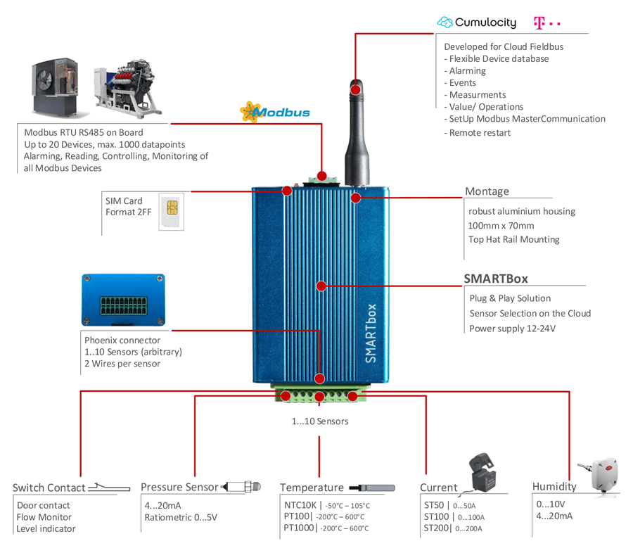
Smartbox, based on the Telit Chipset HE910 is a ready to use solution for connecting Modbus devices to the Cumulocity Fieldbus Cloud. It provides a Master Slave Communication on RS485 for connecting up to 10 devices as well as 10 Sensors (Current ,Temperature, Pressure). Easy configure the SetUp of building automation fielddevices like pumps, e-meters, Airhandling units in the Cumulocity Fieldbus cloud or connect different sensortypes to the box. Using the MQTT protocol the terminal comes up with a low traffic solution for decentralized applications.
| Smartbox IO Overview | ||||
|---|---|---|---|---|
 |
|
|||
 |
Fieldbus |
|
||
| Sensors |
|
|||
 | MQTT Agent for Cumulocity IoT, T-Systems- Cloud der Dinge | |||

For further information:
- please refer to the datasheet provided by PSsystec or download here
- For installing the agent and SW releases, pls refer to Release notes folder of Device guide in Cumulocity or go to: http://cumulocity.com/images/devices/smartbox-release-notes/
- For getting the device pls contact Cumulocity Hardware support or Pssystec (kontakt@pssystec-gmbh.de)
- The full product overview pls download it https://www.pssystec.de/downloads/
Contents
- Wire your Smartbox
- Connect the Smartbox to your Cumulocity Account
- Use the built-in IOs
- Connect a Modbus Device to the SMARTbox
- Use the built-in location functionality
- Use the built-in tracking functionality
- Manage the Agent
- Remotely Manage APN, Tenant, Reboot
- Operate the Device by SMS
- Operate AT commands via device shell
- Local Debug the device
- Help for setting up the items in device database
Wire your Smartbox
- The RelayOutput features an potential free output with 230V max. 2A
- U1 - Common
- U2 - NC
- U3 - NO
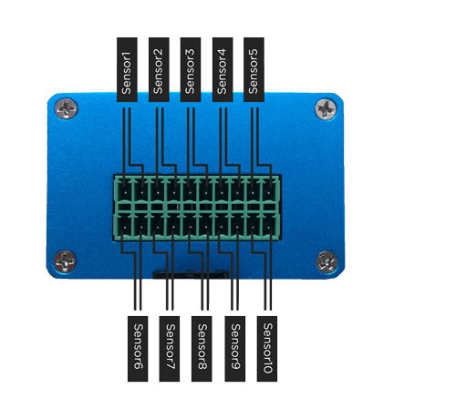
- Connect your sensors, DIN, Analogue Input between Ux and G
- You can use external 24VDC (200mA) or the with the delivered PowerSupply
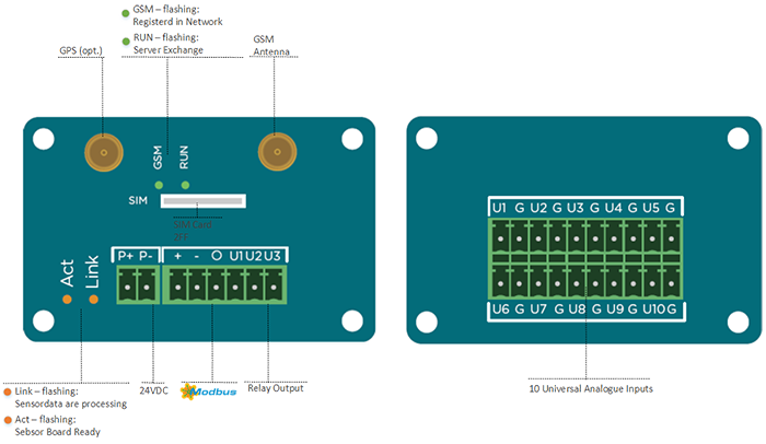
Note that the SMARTbox IO supports:
| PIN SMARTbox | settable Configuration in Cloud (see device Model) | |||||||||||||
|---|---|---|---|---|---|---|---|---|---|---|---|---|---|---|
| G-U1 | 0: inaktiv | 1: PT100 | 2: PT1000 | 3: NTC10K | 4: 0-10V | 5: DI NO | 6: DI NC | |||||||
| G-U2 | 0: inaktiv | 1: PT100 | 2: PT1000 | 3: NTC10K | 4: 0-10V | 5: DI NO | 6: DI NC | |||||||
| G-U3 | 0: inaktiv | 1: PT100 | 2: PT1000 | 3: NTC10K | 4: 0-10V | 5: DI NO | 6: DI NC | |||||||
| G-U4 | 0: inaktiv | 1: PT100 | 2: PT1000 | 3: NTC10K | 4: 0-10V | 5: DI NO | 6: DI NC | |||||||
| G-U5 | 0: inaktiv | 1: PT100 | 2: PT1000 | 3: NTC10K | 4: 0-10V | 5: DI NO | 6: DI NC | |||||||
| G-U6 | 0: inaktiv | 1: PT100 | 2: PT1000 | 3: NTC10K | 4: 0-10V | 5: DI NO | 6: DI NC | |||||||
| G-U7 | 0: inaktiv | 1: PT100 | 2: PT1000 | 3: NTC10K | 5: DI NO | 6: DI NC | ||||||||
| G-U8 | 0: inaktiv | 1: PT100 | 2: PT1000 | 3: NTC10K | 5: DI NO | 6: DI NC | ||||||||
| G-U9 | 0: inaktiv | 1: PT100 | 2: PT1000 | 3: NTC10K | 5: DI NO | 6: DI NC | ||||||||
| G-U10 | 0: inaktiv | 1: PT100 | 2: PT1000 | 3: NTC10K | 5: DI NO | 6: DI NC | ||||||||
| Relay |
|
Note: These Pins are on the backside | ||||||||||||
The connection diagram of the sensors is as follows:
Connect the Smartbox to your Cumulocity Account
Prepare the Cloud and APN
By default the terminal supports cloud fieldbus from Cumulocity. To use it you should:
- Subscribe your account to the Cloud Fieldbus app by contacting Cumulocity support.After this the device Database will be visible in the root folder of Device management. Refer also here: http://cumulocity.com/users-guide/cloud-fieldbus/
- Power on the Terminal and wait until the RUN LED is flashing 2xflash-pause-2xflash-…
- Configure the Terminal’s APN by sending an SMS to Terminal’s SIM card with the following syntax: GPRS=APN,username,password For example, if you have no User and Password then you have to type in your SMS GPRS=<APN>,,
Register the device
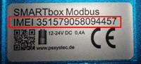
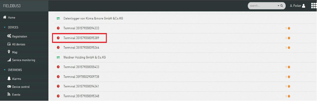
In the cumulocity Devicemanagement go to the menu in Device Registration. Enter the Terminal’s IMEI as an ID. The IMEI is printed on the devices itself:
After accepting the device (this process may tale 30 seconds) you should be able to see it in the All Devices list after a short delay.
Use the built-in IOs
To activate all sensors and Configurable Options proceed as follows:
- Upload the sensor-model in device database. Download the sensorboard model Type https://www.pssystec.de/downloads/ - CloudModels
- Edit the Sensor model if you need it (refer to Configuring Fieldbus device types) but keep the addresses. You will be able to configure for each Input how it should be displayed - You can define each Input as a Measurement or Alarm or event or just a display value. Note that Sensortype is not defined here, but as you will see the parameter which is responsible for the sensortype selection is part of the device model.
- “Add” the sensor Model in Modbus tab on address 1 with Baudrate 19200/8/N/1
- Include the fieldbus widget in the cockpit related to the device and display all items. You can now see all items of the Sensormodel and you can configure the inputs as Temperature sensor or Digitalinputs.
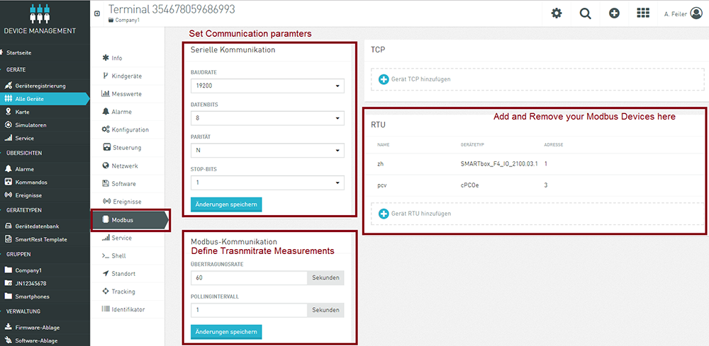
Connect a Modbus Device to the SMARTbox
The Smartbox supports Modbus RTU - all Connections parameters are configurable in the Cloud.
| Connections parameters | ||
|---|---|---|
| Type | Modbus RTU (Master) | Cloud |
| Baudrate | 4800, 9600, 19200, 38400, 115200 (Change during Runtime possible) | Modbus Tab |
| Parity | Even, ODD, NONE (Change during Runtime possible) | Modbus Tab |
| Stopbits | 2,1 (Change during Runtime possible) | Modbus Tab |
| Functioncodes |
|
Device database (model) |
| Datapoints | 1.. 10 Slaves with each 100 datapoints | fix |
| Polling Rate on Bus | 500ms | fix |
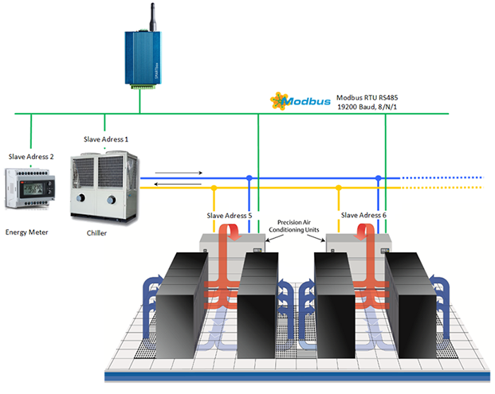
We assume that you already defined your Modbus device(s) which you want to connect in the device database. In this exemplary SetUp you need 4 Models in the device database, which can and should be defined offline in the Cloud (see also chapter Help Device database) Device1: Chiller on Address1 Device2: Energy Meter on Address2 Device3: Frontcooler for Serverline1 on Address5 Device4: Frontcooler for Serverline2 on Address6
To connect 1 Modbus Device to the RTU network:
- Physically wire the Modbus/RTU device through RS485 to the terminal.
- Give the device a unique Modbus address according to the instructions provided with the Modbus device (e.g. by setting a jumper on the device).
- Check the serial communication settings of the device according to the instructions provided with the device (i.e. baud rates and communication protocol). These have to match with all devices on the bus.
- Navigate to the terminal in Cumulocity and click on the “Modbus” tab.
- Change the communication settings shown in the section “Serial Communication” to match the settings on the bus, if needed.
- Change the transmit rate and the polling rate according to your requirements. The polling rate is the frequency at which the Modbus devices are polled for changes. The transmit rate is the frequency where measurements are sent to Cumulocity.
- Click “Save changes” if you made changes.
- To start communication between the terminal and the Modbus device, click “Add new device”.
- Enter a name for the device and select the type of the device from the drop-down box. To add new device types, see “Configuring Fieldbus device types” below. Set the Modbus address of the connected device.
- Click “Add”. Cumulocity will now send a notification to the Modbus terminal that a new device is ready to be managed. This may take a few seconds.
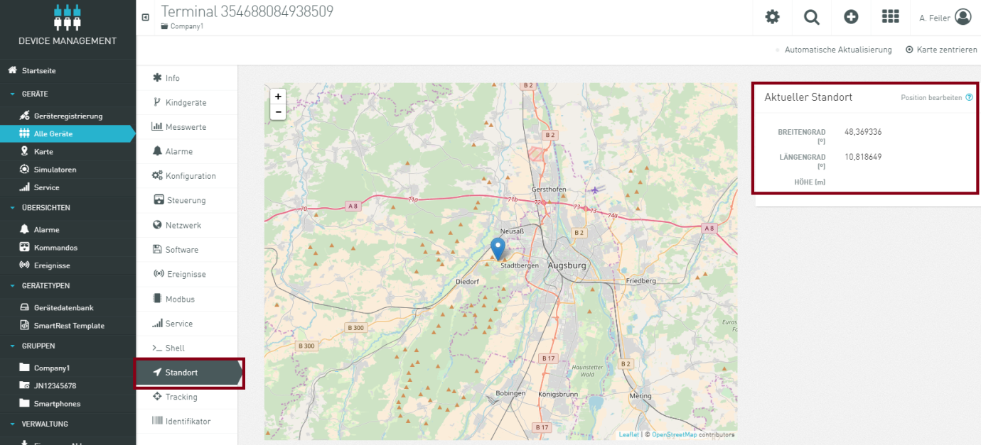
Use the built-in location functionality
The terminal features cell location and is available in Location tab on terminal level. Devices are shown as “pins” that you can click to see the name of the device. Clicking the name of the device takes you to the detailed view of the device. In Smartbox Mini you have 3 Options:
- Using the built in Cell Location. The terminal identifies 3 cells in the near environment and derives the location (default)
- Using the hardware Option with a built in- GPS (this is an extra option). Set c8y.GPS=1 then GPS is enabled. Setting c8y.GPS=0 Cell location is enabled (default)
- Activate a regular identification of the location. In Configuration tab you can set: c8y.LocationCycle=60; define in min, how often the location should be checked. 0 means the cycled checking is disabled. If a value >0 ist set, also the tracking is enabled
Use the built-in tracking functionality
Devices can record the history of their movements in Cumulocity. Using the tracking tab, you can select a time period and visualize the movements of the device during this time period. Movements are shown as red lines on the map.
Next to the map, the individual recordings with their time are listed (“location update events”). When you click a recording, a “pin” on the map will show the location at the time of the recording.
Activate a regular identification of the location. In Configuration tab you can set. If the value of c8y.LocationCycle is greater 0 then tracking is enabled.
![]()
Depending on the type of device and the integration into Cumulocity, you can also configure device-side geo-fencing and motion detection.
Additionally, when the feature is activated, Cell ID information can be used to determine the position of the device. Currently, the services from Combain and Google are supported. The user can see the tracks based on both data, or filter out GPS based data or Cell ID based data.
Manage the Agent
The installed software on the SMARTbox can be remotely managed using the standard software and management feature from Cumulocity, as described in the Device management user’s guide. You can also install the agent manually, follow the instructions here: http://cumulocity.com/images/devices/smartbox-release-notes/
You can get the latest Software version in the Release notes folder of Device guide in Cumulocity or go to: https://www.pssystec.de/downloads/
Remotely Manage APN, Tenant, Reboot
| Remotely Manage APN, Tenant, Reboot | |
|---|---|
| DELETE | deletes the registration in CC and you can register on a new tenant |
| RESET | Restarts the device |
| GPRS=<APN>,<User>,<Password> | Change APN, if no User or Password is required, the fields free |
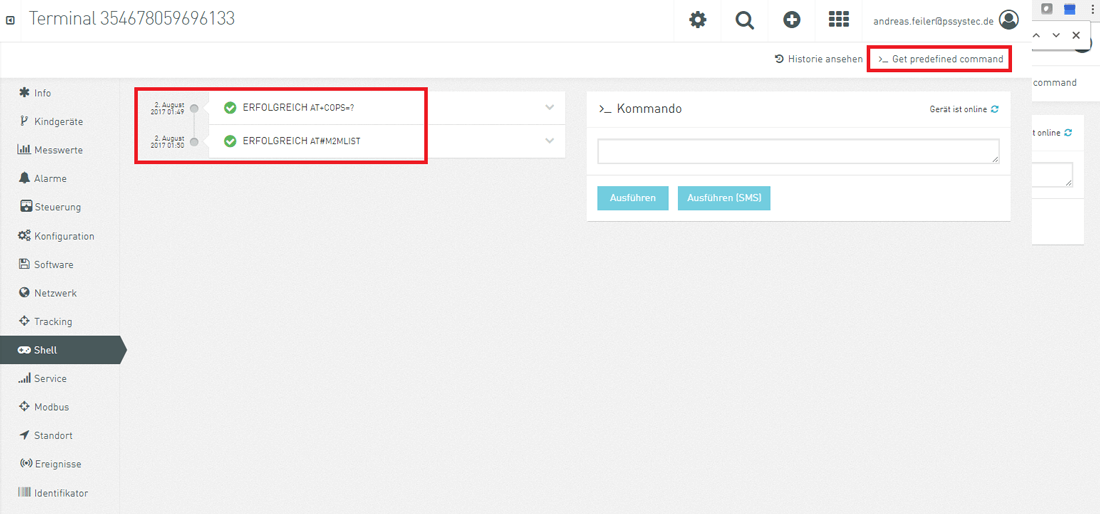
Operate the Device by SMS
Since Agent Version 2.3.x. This service allowing the user to run on the module itself AT Commands sent from a mobile via SMS messages. You will get the answer from the SMARTbox directly on your mobile phone. This allows you, to make troubleshooting in any case of error.
Example: Type AT+COPS? Result on your mobile Phone:
+COPS: 0,0,“Vodafone.de”,2
OK
All AT command supported are listed here: http://www.pssystec.de/downloads/ ➜ supported AT commands and includes a huge amount of different AT commands.
Operate AT commands via device shell
The device shell enables you to read and write configuration parameters to interactively work with remote devices. You can send AT commands in the respective language of the device and view the results of the commands. You can sent any At Command. Check here in Chapter “supported AT commands”: https://www.pssystec.de/downloads/. Frequently used commands are available by clicking the “Get predefined” button.
Local Debug and operate the device
- Install the Telit USB driver on your PC: https://www.pssystec.de/downloads/. The PC will recognize 6 new USB Ports
For debug service:
- Open an Terminal program
- Connect your PC on Telit High Speed Modem USB Port with USB port on the Smartbox
- you will get details of the running machine.
For setting generic AT commands:
- Open an Terminal program
- Connect your PC on USB4 Port with USB port on the Smartbox
- you can set now at commands
Note: Using Agent Versions <2.3.x you have to connect to USB3
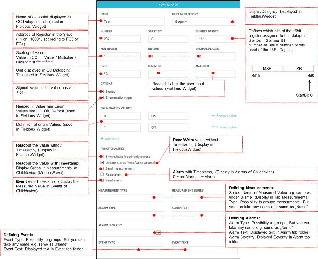
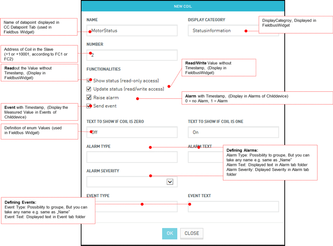
Help for setting up the items in device database
All devices which are connected to the SMARTbox are needed to define in Device Database. The definition includes all supported datapoints of this connected device. Even more, you can not only define the “physical datapoint” like register address, you can also define if this datapoint comes in the cloud as a measurement, event, alarm or write value. In addition some control field per datapoint are available which includes metadata like the Unit or Display Category.