Overview
In the Administration section, you can manage and create machine profiles and line profiles, and you can customize the Machine Park Overview.
You must have ADMIN permission to view and modify the Administration pages.
Managing profiles
In the Profile settings page, you can manage profiles of lines and machines.
The Profile settings page shows a list of all available profiles.
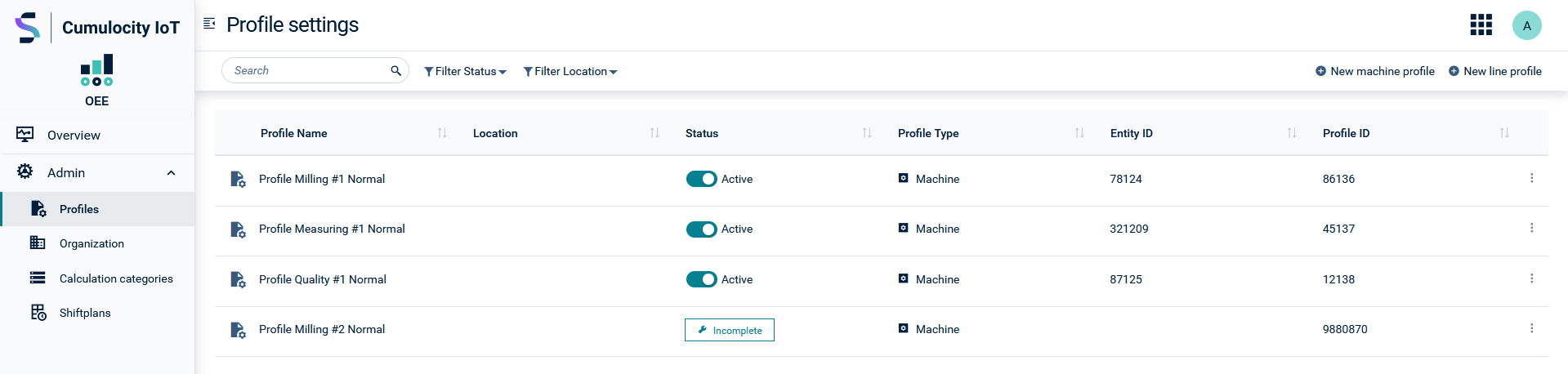
For each profile, the following information is provided:
| Column | Description |
|---|---|
| Profile name | Name of the profile |
| Status | Profile status. One of "Active", "Inactive", "Not complete" |
| Profile type | Type of the profile, either "Line" or "Machine" |
| Entity ID | Unique managed object ID of the machine or line for which the profile calculates the OEE |
| Profile ID | Unique managed object ID of the OEE calculation profile |
To view profile details
Click the arrow icon on the left of an entry to expand or collapse it and show or hide the profile details, for example the machine name and the machine profile in case of machine profiles.
To create a new profile
Click Create new machine profile or Create new line profile at the right of the top menu bar to create a new profile.
For details, see Creating machine profiles or Creating line profiles.
To edit a profile
In the context menu of an entry, click Edit to edit a profile.
To change the the status of a profile
The status column shows the current status of the profile. To switch a completed profile from activated to deactivated and vice versa click the toggle button.
To delete a profile
In the context menu of an entry, click Delete to delete a profile.
For further information on the OEE dashboard, see Dashboards > Machine dashboards.
Creating machine profiles
Click Create a machine profile at the right of the top menu bar to start the configuration of a new machine profile in the profile settings.
Info
After saving the general profile information in the first step you may skip one or more of the following steps and provide the requested information at a later point in time.
Profile
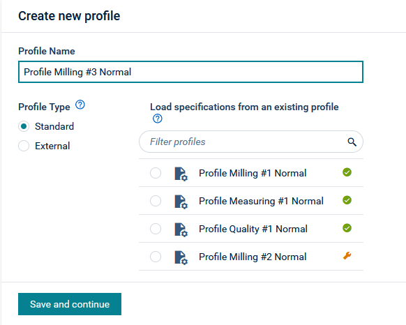
In the first step, you specify the profile name and type.
-
In the Profile name field, provide a name for the new profile.
-
Select the profile type:
Standard profile
To set up a machine profile that is using internal machine data and calculating the values for OEE, Availability, Performance and Quality.At the right, you can select an existing machine profile to use its configuration as a template. After clicking Save and proceed, all settings will automatically be pre-populated with the configuration of the selected profile.
External profile
To integrate external OEE data. It is not possible to define calculation rules or any other settings except the goals for OEE, Availability, Performance and Quality. The tethered external OEE data will be displayed without any calculation. Also no splitting takes place, so the intervals used in the incoming measurements should be configured to match the expectation.The only mandatory measurement is the OEE value itself, whereas measurements for Performance, Availability and Quality are recommended. Technically the measurements must meet the following criteria:
Type/Fragmenttype
- “OEE”
- “Performance”
- “Availability”
- “Quality”
- “PotentialProductionTime”
- “IdealAmount
- “ActualProductionTime”
- “AvailabilityLossTime”
- “AvailabilityLossAmount”
- “IdealProductionAmount”
- “IdealMachineRuntime”
- “ActualProductionAmount”
- “PerformanceLossTime”
- “PerformanceLossAmount”
- “IdealQualityTime”
- “ActualQualityAmount”
- “QualityLossAmount”
- “QualityLossTime”
- “IdealCycleTime”
- “IdealCycleAmount”
Series
- relates to the interval of the profile, so for example for a 10min interval, use “600s”.
Here is a basic example in JSON notation:
{
  "time": "2021-01-01T01:01:01.001Z",
  "id": "123456789",
  "type": "OEE",
  "OEE": {
    "600s": {
      "unit": "",
      "value": 99.306
    }
  }
}
``
-
Click Save and continue to proceed.
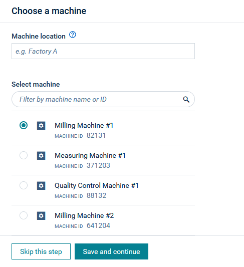
Machine
Next, select a machine to be connected with the profile.
-
At the top, you may optionally enter a machine location. The machine location is used to associate shift plans with the machine. In the Machine location field you can enter free text for any type of location.
-
Select the machine that will be connected with the profile from the provided list. In the search field, you may filter the selection by the machine name or ID. If you have selected an existing machine profile in the previous step, the machine will already be set accordingly.
-
Click Save and continue to proceed.
Info
Once you have saved a profile, the selected machine cannot be changed.
Location
The location indicates where the machine is located. It is used to apply a shift plan to this profile. See Working with shift plans for more details regarding shift plans and the calculation implications.
Workpiece
Next, specify the workpiece.
You can either provide static workpiece information if the machine is always producing the same thing in the same quantity or you can use a production plan, where the workpiece information is provided dynamically at runtime. Note that if you select to use a production plan, OEE calculation will only be performed for times when a production plan is available.
Define a static workpiece
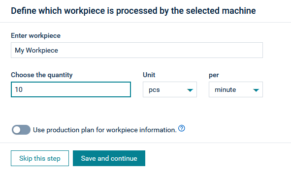
- Provide a name for the workpiece.
- Specify the quantity settings. Enter an amount, a unit (either “pcs” or “CMB”) and a frequency (per minute or second).
Enable a production plan
Activate the toggle Allow production plan workpiece if you want to use a production plan.
The production plan of a machine defines how many products are to be produced at any given time and controls the way the OEE calculation is performed. It provides the baseline for the performance calculation. If no production plan is available, the work piece information from the calculation profile is used.
If the Allow production plan workpiece option is enabled the Ideal Cycle Time (for example 60,000 milliseconds/pcs) from the production plan is used as the Ideal Cycle Time of the OEE calculation.
The OEE application provides a REST API to push the production plans to the application. This REST API can either be invoked from Postman, the Cumulocity IoT UI, or any other system that can access the Cumulocity IoT tenant.
The REST API can be reached at https://[server]/service/oee-bundle/mes/productionplanlist and offers two methods:
-
GET: Retrieve the production plans for the given device. Response might be empty if no production plan was supplied before via the PUT method.
-
PUT: Add or update the list of production plans for the device defined in the body. If a production plan exists for the given tenant and device, the new production plans will be merged internally and obsolete instances will be removed. The resulting production plans will then be sent to the Apama service.
For details, see the Rest API documentation.
Resolution
Next, define the resolution intervals. The default interval is mandatory and will define the interval that is used for this machine in the Overview. It will also influence OEE calculation intervals for sites and lines that do not have a dedicated profile.
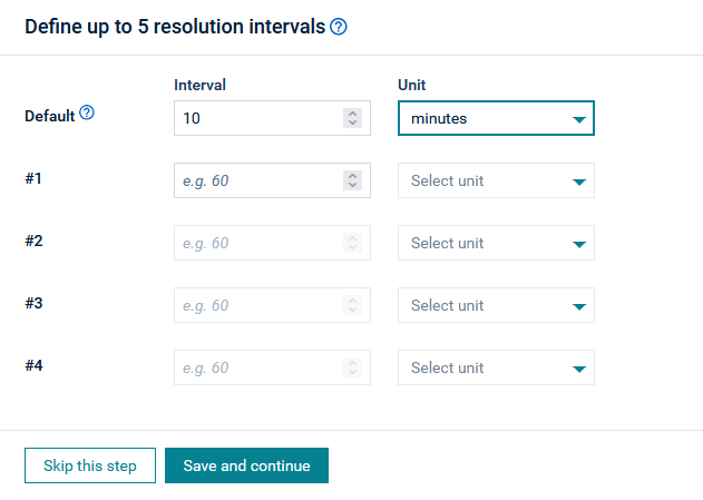
For each resolution interval, provide an interval and a unit (one of min, hour, days).
OEE calculation is performed on the basis of the configured resolution intervals.
Computation
Next, select a calculation method, that means, the values for the mapping of the OEE input variables.
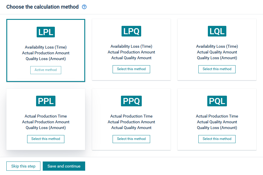
You can select one of six supported calculation methods. The calculation methods differ in what input parameters they require. There are five potential input parameters of which each of the calculation methods requires three. The five input parameters are:
- Actual Production Time
- Availability Losses (Time)
- Actual Production Amount
- Actual Quality Amount
- Quality Losses (Time)
Either Actual Production Time or Availability Losses (Time) are required as the other one can be derived from the one provided. As Actual Production Amount is the sum of Actual Quality Amount and Quality Losses (Time), only two of the three inputs are required as the remaining one can be derived from the other two.
The six calculation methods shown in the screenshot represent the possible combinations of the five input parameters following the rule described above.
For more information on the input variables and the naming conventions of the pathways, see OEE theory.
Info
For the calculation methods 2 & 5 (PQL & LQL), you should not use “status event” in the mapping formula for both Actual Quality Amount and Quality Losses (Amount), because as a sum they form the Actual Production Amount. Unlike the other calculation methods, no subset of the Actual Production Amount can be derived using the “status event”, since calculation methods 2 & 5 only consist out of subsets.
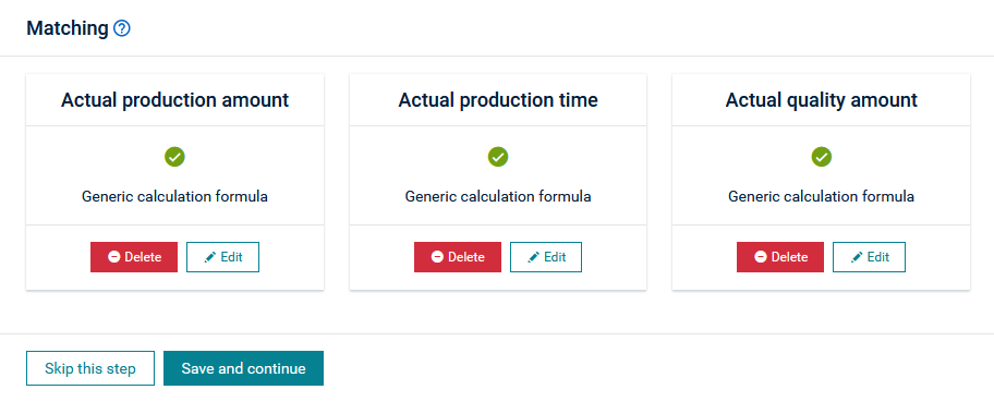
Matching
Next, define rules to determine which machine data is used for the OEE input variables.
For details on matching data, see Matching data.
Short stoppages
Optionally, you can record short stoppages. By default, short stoppages are not tracked.
- Select Yes, should be tracked to turn on the tracking.
- Provide a duration in minutes and click Save and Proceed.
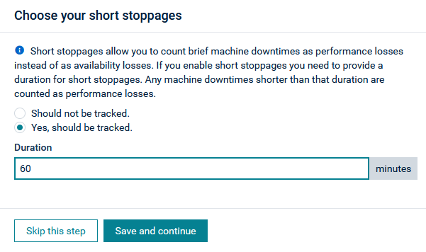
All Availability Losses shorter than the set duration are no longer treated as Availability Losses but instead as Performance Losses. When the duration is set to one minute and an Availability Loss (time) is shorter than 60 seconds it will be deducted from the Availability Losses (time) and added to the Performance Losses (time) and the Actual Production Time.
Info
Short shutdowns currently only work if the Actual Production Time or the Availability Losses (time) are configured via machine status events. The reason is that you can only properly observe machine uptime or downtime with machine status events and thus correctly detect if a shutdown is a short shutdown. With transformation rules you actually get one value for the whole interval and it is unclear if the Availability Loss Time is one long shutdown or consists out of multiple short shutdowns.
Goals
Next, you may specify OEE target goal values in percentage. These values will be displayed in the Andon Board.
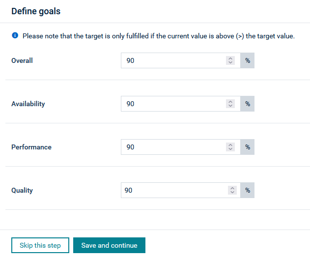
Info
The target is only fulfilled if the current value is above (>) the target value.
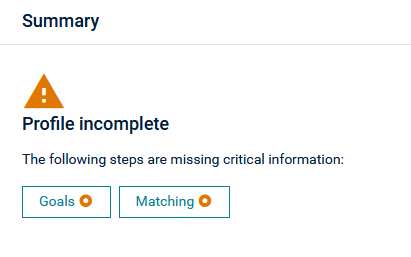
Summary
Finally, the summary shows if the profile configuration is complete or if any (and which) information is missing.
Creating line profiles
The following section walks you through the steps required to create a new line profile.
Step 1 - Create a new site
Since lines are attached to a site or an area, you must first have such an entity available.
Switch to the Organization page under Administration and create a new site as described in Organization > To create a new entity.
You can skip this step if you have already a site or area available to which you want to attach the new line profile.
Step 2 - Create a new line
Next, create a new line in a similar way, this time selecting “Line” as entity type.
Step 3 - Attach the line to a site
- Click the Add button on the site to which you want to attach a line (entity).
- Select your desired line and click Add.
The line will be added to the site in the Organization structure and get represented in the Machine Park Overview.
Step 4 Add machines to the line
- Click the Add button at the right of the line.
- Select the machines you want to assign to the line and click Add.
Step 5 - Create a line profile
Switch to the Profile Page under Administration. Click Create a line profile at the right of the top menu bar to start the configuration of a new line profile in the profile configurator.
-
In the first step (Profile), specify a profile name and type (either Standard profile or External profile). As with machine profiles, you can also create a new line profile based on an existing profile.
-
Next, select a line.
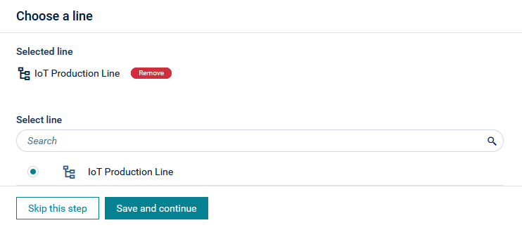
- Continue with the line mapping. You can now use the data of the machines you have previously assigned to the line.
For details on all steps of the profile configuration refer to Creating machine profiles.
Step 6 - Activate the line profile
To complete the creation of a new line profile, activate it in the Profile settings page. For more information see also Managing profiles.
Info
Make sure that all machine profiles of the line are activated as well.
Calculation example of a line profile
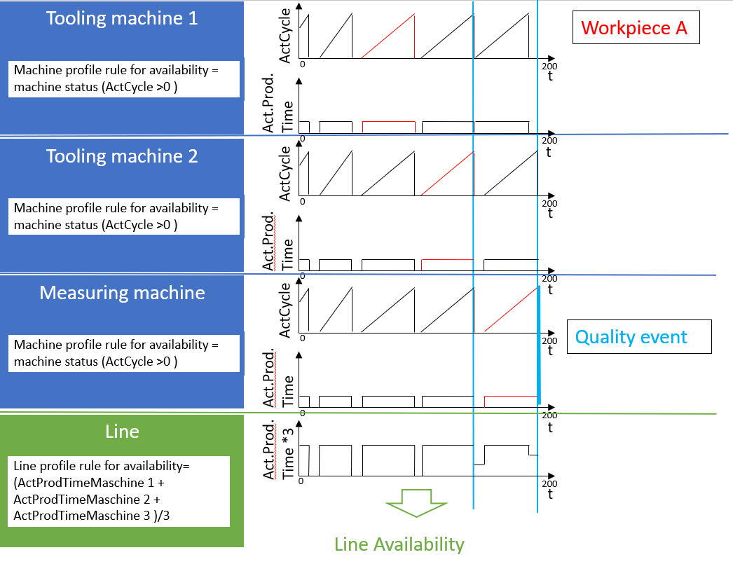
Initial situation
In a production line there are two machine tools and one measuring machine in a row. The workpiece first passes through machine tool 1, then machine tool 2 and finally the measuring machine.
The quality of the workpiece is measured at the measuring machine and not derived from the process parameters of the machine tools.
Calculation of the Availability
To calculate the Availability of the entire line, all three machines are considered. For each machine a machine profile is created which determines the production time based on the measured value “ActCycle”, see the image below.
To calculate the Availability of the line, all three values (Actual Production Time) of the machine profiles are combined and divided by the number of machines. The aim here is a static consideration of Availability and no Availability is calculated in relation to a single workpiece. In this respect, this logic is also applicable to discrete as well as process manufacturing.
Calculation of the Performance
The run rate is determined at the bottleneck machine, for example at the output rate of the last machine, here the measuring machine. Thus, the total run time of the workpiece is not considered.
Calculation of the quality
The quality quantity is derived directly from the quality events. This event is generated by the measuring machine.
Matching data
In the Matching section of a profile configuration, you define rules to determine which machine data is used for the OEE input variables.
Overview
The following image provides an overview on the matching capabilities.
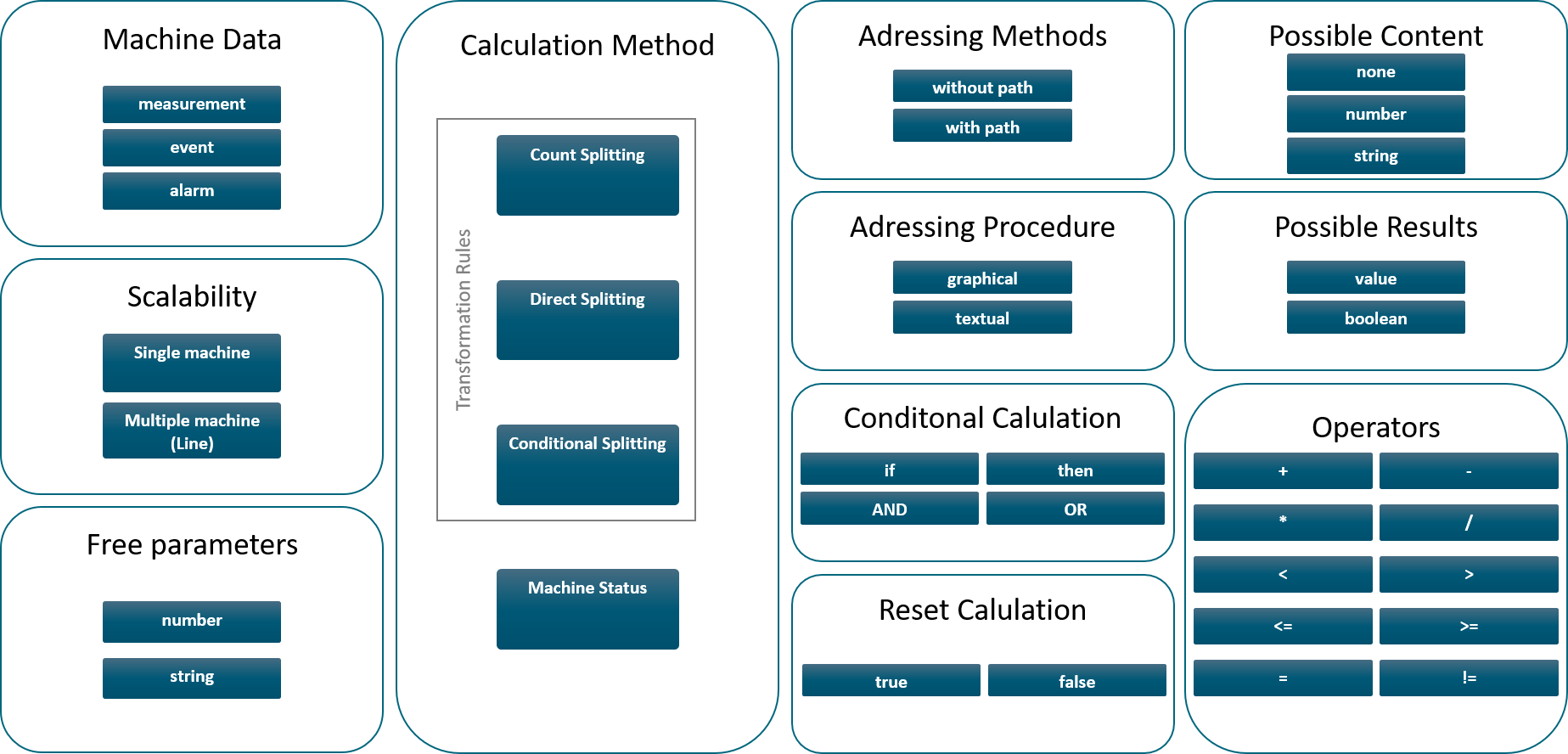
You can either define a single calculation rule or use categories to define at least two separate calculation rules for an input variable. The categories must be created under Calculation categories first, see Calculation categories. Using categories to define multiple calculation rules can for example be used to define different rules for different kinds of losses (planned vs. unplanned) or to distinguish multiple sources of amounts. The different categories are calculated individually and then aggregated to the final input variable. In the chart of the Machine Dashboard it is possible to not only show the aggregated input variable but also the graphs for the individual categories.
Calculation rules
Calculation rules can be defined as
-
Transformation rules (“Define quality status event” or “Define machine status event” is not activated): The result of transformation rules is a value. This enables you to count parts, for example, and thus determine the Actual Production Amount.
-
Machine status events (“Define quality status event” or “Define machine status event” is activated): The result machine status events is a Boolean. Here you can specify, for example, that all parts of the Actual Production Amount are counted towards the Actual Quality Amount while the machine has sent the status “Quality OK”. In contrast to the other calculated values, which have a retroactive effect, this will count for upcoming measurements, events. Machine status is possible for the input variables: Actual Production Time, Availability Losses, Actual Quality Amount and Quality Losses. See the example mappings below.
Calculation reset
You can keep input values valid as long as a new value arrives, that replaces the old one, (false) or you can delete the value after using it once and stop the calculation until a new value arrives, which replaces the old one (true).
Example:
measurement(564135,Drill machine 500,ActCycle,ActCycle,false)
If the value is false, the calculation can be continued with an old value for the Quality, whereas if the value is true, the calculation is performed only once, if the Quality value was the last missing part for the calculation.
Providing fixed values for inputs & KPIs
If you want to have fixed KPIs or inputs follow these instructions:
Fixed KPIs
- Fixed Quality: Define the Actual Quality Amount or Quality Loss (amount) and take the Actual Production Amount formula and multiply it by the intended quality factor.
- Fixed Availability: Define a formula for Actual Production Time or Availability Loss (time) using the intended availability factor multiplied by the constant “intervalLength”, for example “0.8 * intervalLength” for availability 80%.
- Fixed Performance: Does not make much sense as it is dependant on multiple inputs.
Fixed Inputs
- Actual Production Time: Can be provided as a static value, use “intervalLength” to ensure correct value per interval.
- Availability Loss (time): Can be provided as a static value, use “intervalLength” to ensure correct value per interval.
- Actual Production Amount: Needs to be derived from actual measurements.
- Actual Quality Amount & Quality Loss (amount): Can be defined as fraction of the Actual Production Amount using the same formula multiplied by fraction. Exceptions approach in calculation method 2 & 5 as they do not include the Actual Production Amount. Actual Quality Amount and Quality Loss (amount) must be defined.
Conditional splitting
The Actual Production Amount can be determined, among other methods, with an IF-THEN rule.
In this example we derive the produced amount from an event “StateEvent” of the machine “Slicer”. As soon as the “content$sub_state$id” of the event has the content “3”, it can be deduced that a workpiece has been produced. The same also works for measurements or alarms.
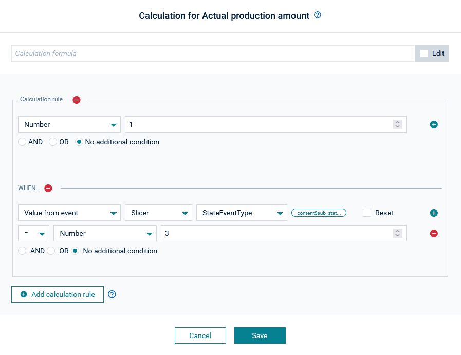
This rule looks like this in text form: “if evt(“342”, “StateEvent”, “content$sub_state$id”,false) = 3 then 1”
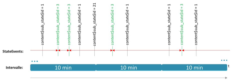
If the IF condition is fulfilled, this means for the OEE application that a workpiece has been created, see green events.
If an IF condition is fulfilled, the created workpiece (quantity = 1) is split up to the last event, regardless of whether the event fulfills the If condition or not. The splitting is shown in red.
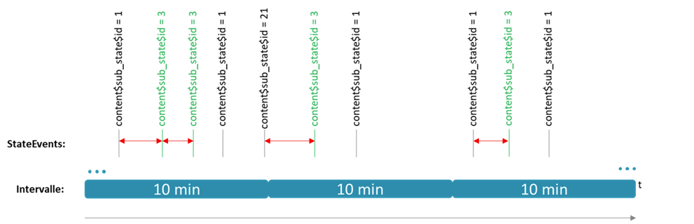
This logic can also be applied to the Actual Quality Amount and Quality Loss Amount.
Of course, all three input parameters can also be derived directly from MEAs, or the number of an MEA. The Actual Quality Amount and Quality Loss Quantity can also be determined by the machine status.
Measurements
The following image provides an overview on the matching capabilities for measurements.
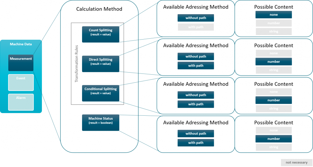
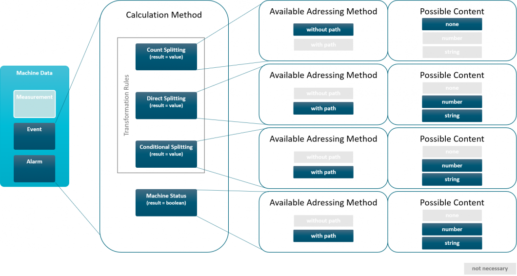
Events & alarms
The following image provides an overview on the matching capabilities for events and alarms.
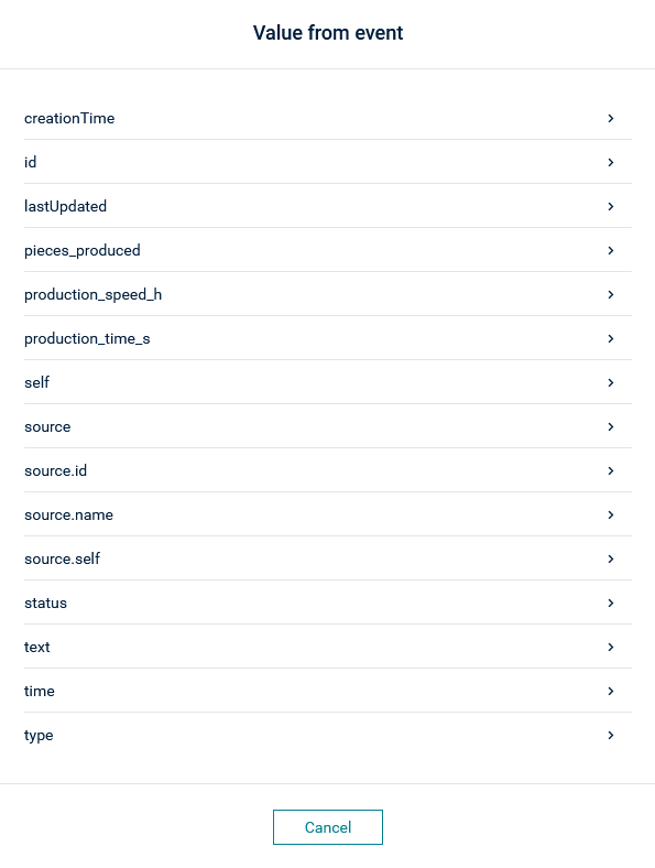
Events with path
There is no limit on the number of event types, but for each type there is a limit (150) to the number of unique paths that are stored.
Is it also possible to manually address events with path through the text editor during mapping if the 150 paths are not sufficient.
Example matching
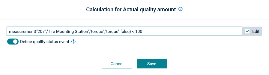
Machine status events for the Actual Quality Amount
This is an example of the case “Define quality status event” for the Actual Quality Amount:
If the measurement “torque” is below 100, the condition evaluates to “true” indicating good quality. All new produced parts (Actual Production Amount) are now counted as good parts towards the Actual Quality Amount while “torque” stays below 100.
Using IF-THEN in a machine status
Assume for example, that there is an event that is telling what is being produced (=flowing through a pipe) and besides that there is a measurement that represents the pressure on a sensor. The threshold pressure signalling that the machine is producing or that the quality is OK might be dependent on the product that is being produced. This can be captured by this:
if event(...) = "productA" then measurement(...) > 300.0; if event(...) = "productB" then measurement(...) > 210.0
So if productA is produced and the pressure is above 300 the machine status for Actual Production Time will be true and the future timeframe will be valued as Production Time.
Organization
In the Organization page under Administration, you can customize the Machine Park Overview. Various entities (that is, sites, areas and lines) can be created from here and can be arranged according to your needs.
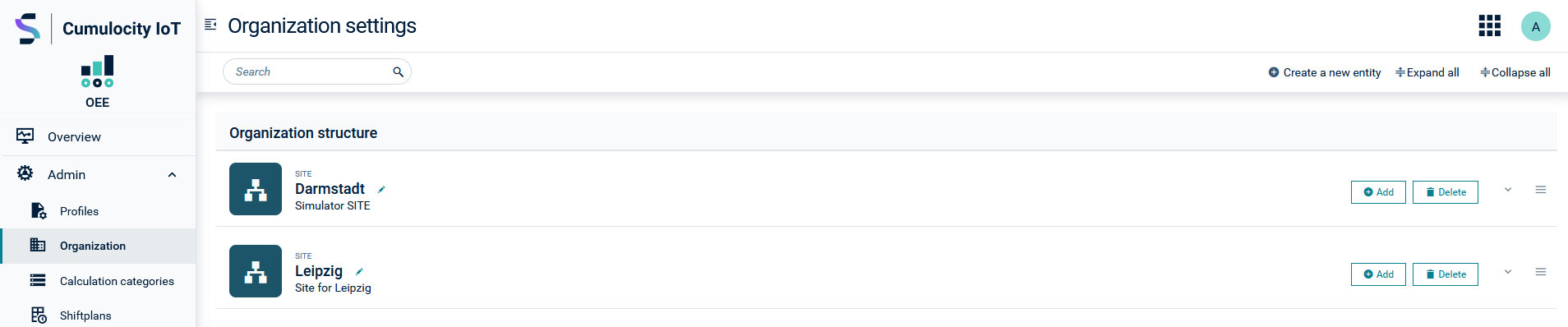
The Organization structure area reflects the structure of the Machine Park Overview.
The entities listed in the Unassigned entities area, are not shown in the Machine Park Overview and no calculation is performed for them.
Click the arrow icon at the right to expand or collapse the entity and show or hide its details.
To create a new entity
- Click Add a new entity at the right of the top menu bar to create a new entity.
- In the dialog box, select the entity type (one of “Site”, “Line”, or “Area”).
- Enter a unique name for the entity (mandatory) and an optional description.
- Specify a value for the OEE target in percent.
- Click Add to add the new entity.
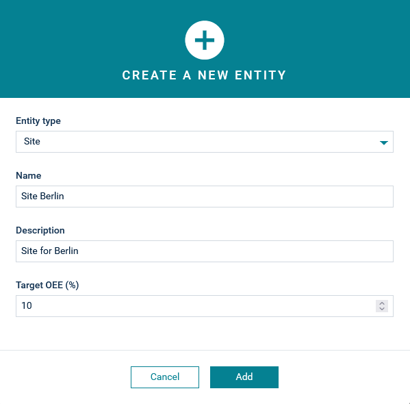
The entity will be added to the bottom of the Organization page under Unassigned entities.
Lines must be assigned to sites or areas.
To edit an entity
Click the pencil icon next to the entity name to open the entity editor and edit the entity.
To assign an entity
Click the Add button to add an entity (line, area, or machine) to another entity. You can assign one or more machines to multiple lines. This allows for modelling of setups where lines can split, join, or share equipment between them.
Example: To attach a line to a site
- Click the Add button on the site to which you want to attach a line (entity).
- Select your desired line and click Add.
The line will be added to the site in the Organization structure and get represented in the Machine Park Overview.
To unassign an entity
Click the Unassign button at the right of an entity to unassign a previously attached entity.
To delete an entity
Click the Delete button at the right of an entity to delete (and unassign) an entity.
Deleting an entity will result in unassigning all entities previously assigned to this entity.
To rearrange entities
Entities can be easily re-organized under Organization structure and Unassigned entities by drag-and-drop. Any changes here are reflected in the Machine park Overview. Note that entities may only be re-organized by drag-and-drop within their parent entity. If you want to change an entity’s parent, this must be done using the assignment. That is, it must be unassigned from the old parent, and then re-assigned elsewhere.
Calculation categories
Calculation categories can be used to provide multiple calculation rules for the same input variable. The calculation rules together make up the input variable.
This allows you to define multiple rules that will handle different types of losses, for example, planned versus unplanned, or to distinguish between multiple sources of incoming data. Each category will be calculated individually and then aggregated to give the final input variable. Further information on the creation of calculation profiles can be found in Matching data.
Using calculation categories
In order to use a calculation category in your OEE calculation profiles, the category itself must first be created in Administration > Calculation Categories in the application. Categories are considered specific to a given input parameter. So, for each input parameter that requires the use of categories, the input parameter must have its categories defined before the input parameter itself can be created. Typically, calculation categories are used when at least two different types of calculation must be combined in order to form an input parameter.
-
Example 1: You may wish to have “Planned Maintenance” and “Manual Stoppage” categories for the Availability Loss (Time) input in order to distinguish these two different kinds of losses from each other.
-
Example 2: You may wish to use “Source Left” and “Source Right” categories for Actual Production Amount in order to distinguish the different incoming paths a machine has for its input items.
Info
As categories may be used in many different OEE calculation profiles, it is not possible to remove a category from the application once it is created. It is therefore important to consider the categories to be used and ensure that they make sense long-term. If an old category should no longer be used, it may be set to “deactivated”. This will prevent it from being used in any new calculation profiles.
Working with shift plans
Shift plans are optional and control the way the OEE calculation is performed. The shift plan tells the OEE application when production is planned to happen as opposed to breaks, refitting times, and non-production times (for example, weekends). It provides the baseline for the Availability calculation. If no shift plan is provided, it is assumed the machine is running 24/7 for 100% Availability.
Each known location can have a shift plan which consists of one or more shifts. You create a location by assigning it to a machine profile. A shift defines the time when all machines in this location are in a specific mode, that is, in production or non-production mode.
If a machine is in production mode, it is running and produces goods. If it is non-production mode, it might be in maintenance or there might be a staff break. During non-production mode no goods are being produced.
The OEE application takes these shift definitions into account when calculating the OEE values, especially the Availability and the Ideal Production Time.
A shift can be defined to be an one-off event for a specific date/time (for example, for a public holiday) or a recurring instance. The recurring shifts are typically used to define morning or evening shifts that are scheduled every working day in every week.
If there are overlapping shifts defined, the shifts are handled in the following decreasing priority:
- non-recurring non-production
- non-recurring production
- recurring non-production
- recurring production
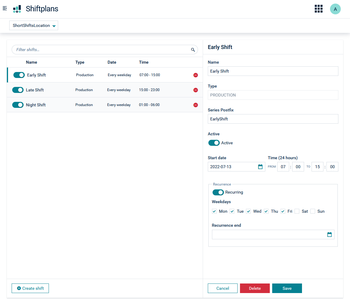
To create a shift
- Select the appropriate location in the dropdown menu at the top of the screen.
- Click Create Shift to add a new shift to the selected location.
- Fill in all required details in the form on the right-hand side.
- Click Save to save the shift.
To change a shift
- Select the row of the shift that you want to update.
- Update the required fields.
- Click Save to save the shift.
Be aware that a non-recurring shift cannot be edited if it is currently running. If you edit a recurring shift, the changes only affect the instances that start after you saved it. No current running shift is altered.
To delete a shift
- Click the red icon in the row of the shift that you want to delete.
- Alternatively, select the row of the shift that you want to delete and then click Delete on the bottom right-hand side.
The OEE application provides a REST API to work with the shift plans which can either be invoked from the go-c8y-cli and its OEE extension, Postman, or any other system that can access the Cumulocity IoT tenant.
For details of the API, see the REST API documentation.