# Cloud Fieldbus
Source: https://cumulocity.com/docs/device-integration/cloud-fieldbus/
Sector: Device management & connectivity
Release: Latest
Description: Connect fieldbus devices, manage them remotely, and configure, export, and import the device protocols that map their data.
## Introduction
Cloud Fieldbus enables you to connect any fieldbus device to Cumulocity. This connection can be done within minutes and at minimal cost and provides high levels of security and reliability. Connected devices can be completely managed from Cumulocity including data collection, visualization, fault management and remote control.
With Cumulocity Cloud Fieldbus you can collect data from fieldbus devices and remotely manage them. This section describes how to
* [Connect](https://cumulocity.com/docs/device-integration/cloud-fieldbus/#connecting-fieldbus) fieldbus devices to Cumulocity.
* [Manage](https://cumulocity.com/docs/device-integration/cloud-fieldbus/#managing-fieldbus) the connected fieldbus devices.
* [Configure](https://cumulocity.com/docs/device-integration/cloud-fieldbus/#configuring-fieldbus) the remote management capabilities of particular types of devices and [import and export](https://cumulocity.com/docs/device-integration/cloud-fieldbus/#exporting-importing-protocols) them.
Cloud Fieldbus is supported out of the box by several devices. For information on supported devices, refer to the [Cumulocity Partner Devices Ecosystem](https://ecosystem.cumulocity.com/devices/?filter_cumulocity_certified=yes) which allows to filter for all devices which offer full functional support with Cloud Fieldbus.
> **Info:**
> To support Cloud Fieldbus with your terminal please contact [product support](https://cumulocity.com/docs/additional-resources/contacting-support/).
## Connecting fieldbus devices
For the following instructions, it is assumed that you have a Cloud Fieldbus terminal available and it is registered as a device in your Cumulocity tenant. To register a terminal with Cumulocity, follow the instructions provided with the terminal.
### Connecting Modbus/RTU devices {#connecting-modbusrtu-devices}
To connect a Modbus/RTU device, follow these steps:
1. Physically connect the Modbus/RTU device through a RS-485 or RS-232 cable to the terminal.
2. Assign the device a unique Modbus address according to the instructions provided with the Modbus device (for example by setting a jumper on the device).
3. Check the serial communication settings of the device according to the instructions provided with the Modbus device (that is, baud rates and communication protocol). These must match with all devices on the bus.
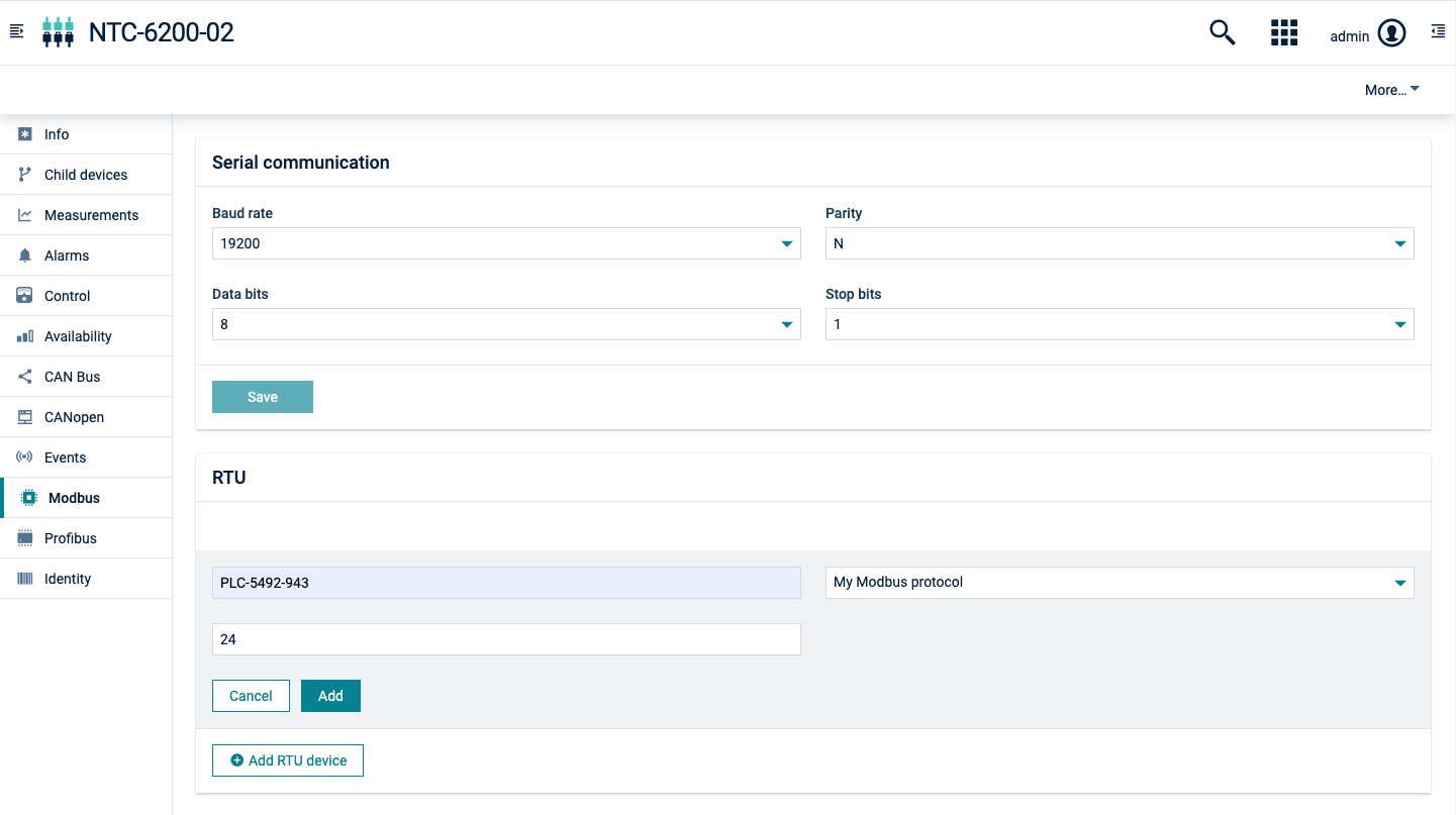
4. In the Device Management application, click **All devices** in the **Devices** menu in the navigator. In the device list, select the terminal and switch to the **Modbus** tab.
5. Change the communication settings shown in the **Serial communication** section to match the settings on the bus, if needed.
6. Change the transmit rate and the polling rate according to your requirements. The transmit rate is the frequency where measurements are sent to Cumulocity. The polling rate is the frequency at which the Modbus devices are polled for changes.
7. Click **Save** to save your settings.
#### To add child devices {#to-add-child-devices}
1. To start the communication between the terminal and the Modbus/RTU device, click **Add RTU device**.
2. Enter a name for the device and select the device protocol from the dropdown field. See [Configuring fieldbus device protocols](https://cumulocity.com/docs/device-integration/cloud-fieldbus/#configuring-fieldbus) for information on how to add a new device protocol. Set the Modbus address of the connected device.
3. Click **Add**. Cumulocity will now send a notification to the Modbus terminal that a new device is ready to be managed. This may take a few seconds.
After completion, a new child device has been added to the terminal and can now be managed. You can click on the name of the device in the list to navigate to the device. If you have not yet added Modbus devices to the terminal, you may have to reload your browser window to make the **Child Devices** tab visible.
### Connecting Modbus/TCP devices {#connecting-modbustcp-devices}
To connect a Modbus/TCP device, follow these steps:
1. Make sure that the Modbus/TCP device is connected to the terminal, that is, directly through an Ethernet cable or through a switch. If you are using a Modbus gateway, configure the gateway in a way it can communicate with the Modbus devices behind the gateway.
2. Check the network settings of the device using the instructions provided with the device.
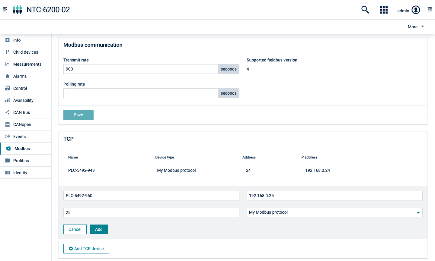
3. In the Device Management application, click **All devices** in the **Devices** menu in the navigator. In the device list, select the terminal and switch to the **Network** tab. Verify that the LAN settings of the terminal match the settings of the device so that TCP communication can be established.
4. Switch to the **Modbus** tab.
5. Change the transmit rate and the polling rate according to your requirements. The transmit rate is the frequency at which measurements are sent to Cumulocity. The polling rate is the frequency at which the Modbus devices are polled for changes.
6. Click **Save** to save your settings.
#### To add child devices {#to-add-child-devices}
1. To start the communication between the terminal and the Modbus/TCP device, click **Add TCP device**.
2. Enter a name for the device and select the device protocol from the dropdown field. See [Configuring fieldbus device types](https://cumulocity.com/docs/device-integration/cloud-fieldbus/#configuring-fieldbus) for information on how to add a new device protocol. Set the Modbus address and the IP address of the connected device.
3. Click **Add**.
Cumulocity will now send a notification to the Modbus terminal that a new device is ready to be managed. This may take a few seconds.
> **Info:**
> It is assumed that all Modbus/TCP communication uses the standard Modbus/TCP port 502. On the NTC-6200 and NTC 220 series, the port to be used can be configured through the variable "service.cumulocity.modbus.port" via the device shell or the local web user interface of the device.
### Connecting CAN devices {#connecting-can-devices}
To connect a CAN device, follow these steps:
1. Physically connect the CAN device to the terminal.
2. Check the serial communication baud rate of the device according to the instructions provided with the device. These must match all devices on the bus.
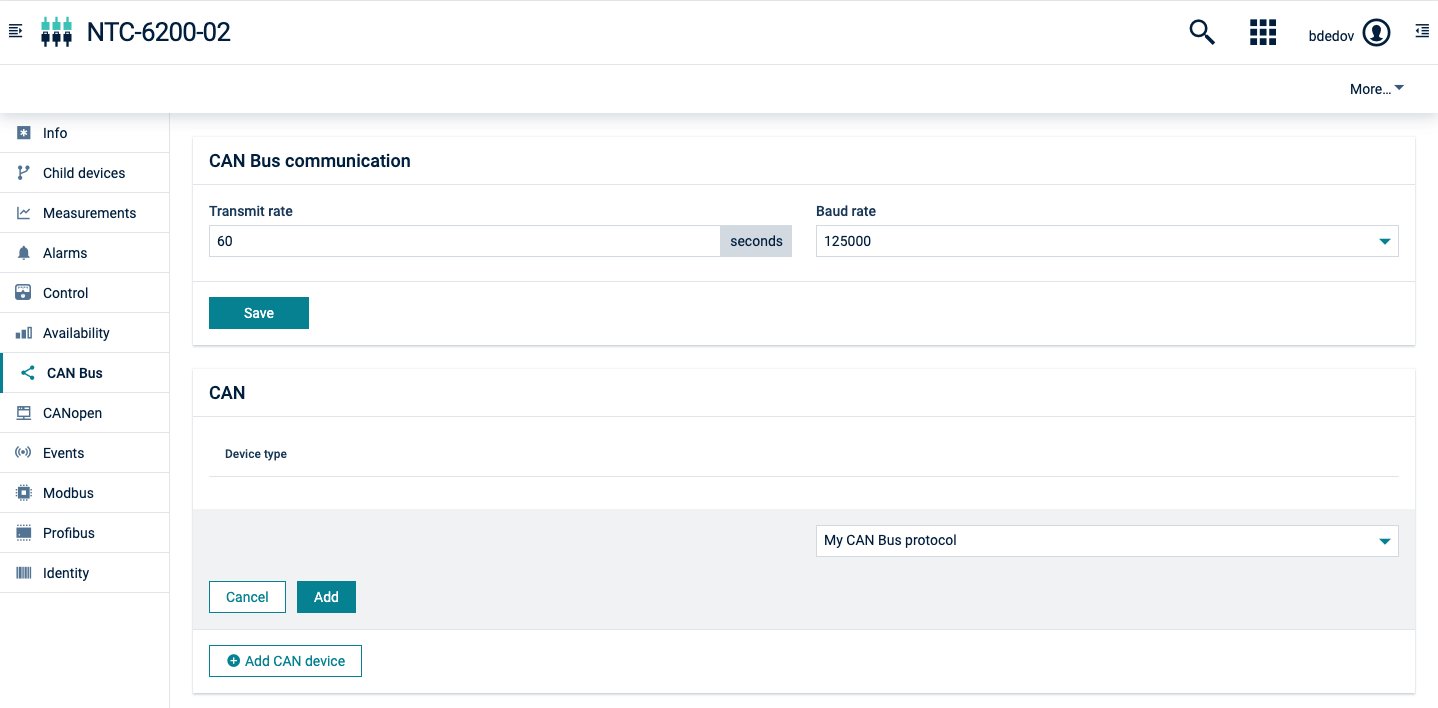
3. In the Device Management application, click **All devices** in the **Devices** menu in the navigator. In the device list, select the terminal and switch to the **CAN Bus** tab.
4. Change the baud rate setting shown in the section **CAN Bus communication** to match the settings on the bus, if needed.
5. Change the transmit rate according to your requirements. The transmit rate is the frequency where measurements are sent to Cumulocity.
6. Click **Save** to save your settings.
#### To add child devices {#to-add-child-devices}
1. To start the communication between the terminal and the CAN device, click **Add CAN device**.
2. Enter a name for the device and select a device protocol from the dropdown field. See [Configuring fieldbus device types](https://cumulocity.com/docs/device-integration/cloud-fieldbus/#configuring-fieldbus) for information on how to add a new device protocol.
3. Click **Add**.
Cumulocity will now send a notification to the fieldbus terminal that a new device is ready to be managed. This may take a few seconds.
After completion, a new child device has been added to the terminal and can now be managed. You can click on the name of the device in the list to navigate to the device. If you have not yet added fieldbus devices to the terminal, you may have to reload your browser window to make the **Child devices** tab visible.
### Connecting Profibus devices {#connecting-profibus-devices}
Connecting Profibus devices slightly differs from the regular plug & play approach of other Cloud Fieldbus protocols. The gateway acts as a device on the Profibus so it can easily be integrated into an existing infrastructure. This means that Profibus data must be actively sent to the gateway though. Typically, this is done by programming a PLC to actively send information to the gateway via its configured Profibus device address.
To connect a Profibus device, follow these steps:
1. Physically wire the Profibus device to the terminal.
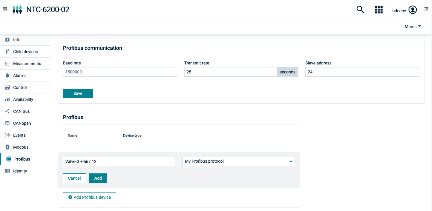
2. In the Device Management application, click **All devices** in the **Devices** menu in the navigator. In the device list, select the terminal and switch to the **Profibus** tab.
3. The baud rate is automatically detected by the gateway and it is displayed here.
4. Change the transmit rate according to your requirements. The transmit rate is the interval at which measurements are sent to Cumulocity.
5. Set the device address of the terminal.
6. Configure your Profibus controller to communicate to that device address. To do so, refer to the gateway manual (see for example Smart box at the [Cumulocity Partner Devices Ecosystem](https://ecosystem.cumulocity.com/devices/?filter_cumulocity_certified=yes)).
7. Click **Save** to update the gateway with the new settings.
#### To add child devices {#to-add-child-devices}
1. To start the communication between the gateway and the Profibus device, click **Add Profibus device**.
2. Enter a name for the new device.
3. Select the device protocol from the dropdown field. See [Configuring fieldbus device types](https://cumulocity.com/docs/device-integration/cloud-fieldbus/#configuring-fieldbus) for information on how to add a new device protocol.
4. Click **Add** to confirm and notify the gateway.
Now a child device will be created containing the data configured in the selected device protocol.
Cumulocity will notify the gateway to send data for the newly created child device.
## Managing fieldbus devices
Once connected, you can now manage your device. Switch to the **Child devices** tab of a device to list the connected fieldbus devices and navigate to a fieldbus device.
Depending on the capabilities of the device and its configuration in Cumulocity, you can:
* [Collect measurements](https://cumulocity.com/docs/device-integration/cloud-fieldbus/#collecting-measurements)
* [Send alarms on coil or register changes](https://cumulocity.com/docs/device-integration/cloud-fieldbus/#monitoring-alarms)
* [Log coil and register changes as events](https://cumulocity.com/docs/device-integration/cloud-fieldbus/#logging-events)
* [Monitor the status of coils and registers](https://cumulocity.com/docs/device-integration/cloud-fieldbus/#monitoring-the-device-status)
### Collecting measurements {#collecting-measurements}
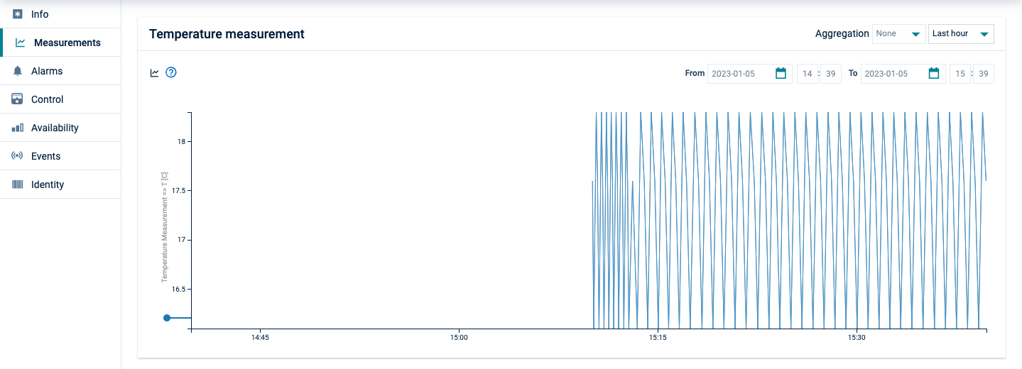
If the device protocol of the fieldbus device is configured to collect measurements, these will be visible in the **Measurements** tab. They will also be available for usage in the [Data explorer](https://cumulocity.com/docs/cockpit/data-explorer) and in [dashboards](https://cumulocity.com/docs/cockpit/working-with-dashboards/).
Data is collected according to the interval specified in the "transmit rate" property of the terminal as described above. To optimize the data traffic, data which is exactly the same as collected previously may not be sent again.
### Monitoring alarms {#monitoring-alarms}
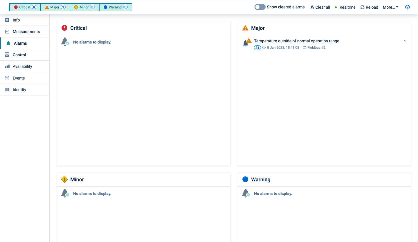
If the device protocol of the fieldbus device is configured to send alarms, these will be visible in the **Alarms** tab and usable in widgets. To determine the alarm status, the fieldbus devices are monitored for changes according to the "polling rate" setting of the terminal. If a particular coil or register is non-zero, an alarm will be raised. If the value goes back to zero, the alarm will be cleared.
### Logging events {#logging-events}
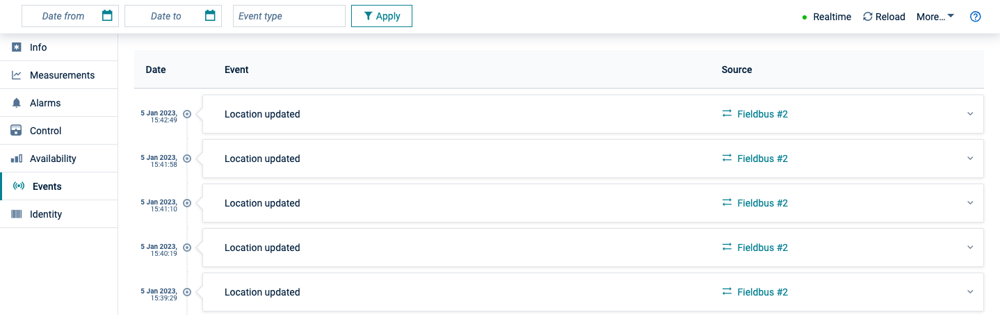
Similar to alarms, changes in fieldbus devices can be monitored and logged as events. Each time, the value of the monitored coil or register changes, an event is created. You can see the events in the **Events** tab of the device or use them in widgets. You can inspect the new value of the monitored coil or register by clicking on the event and unfolding the event details.
### Monitoring the device status {#monitoring-the-device-status}
The status of devices can be monitored in realtime using dashboard widgets in the Cockpit application. Navigate to the Cockpit application, create a dashboard or report, and add widgets as described in [Cockpit](https://cumulocity.com/docs/cockpit/).
### Monitoring the device status using the Fieldbus device widget {#monitoring-the-device-status-using-the-fieldbus-device-widget}
The "Fieldbus device" widget provides you with a tabular display of the status of a device. The status of the device can also be modified through the widget.
To use the "Fieldbus device" widget, follow these steps:
1. Select a dashboard and click **Add widget** in the top menu bar.
2. Select the "Fieldbus device" widget and edit the title of the widget.
3. Select the device that should be shown in the widget in the **Asset selection** section.
4. Select the coils and registers to be shown on the widget.
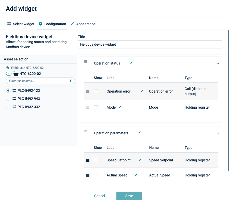
In the widget, the selected coils and registers are grouped into display categories as configured in the device protocol. The "Fieldbus device" widget updates automatically as soon as there is new data available. You do not need to click **Reload**.
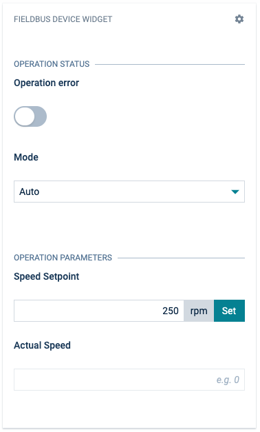
Registers and coils that can be changed are represented by active widgets. If you click a switch, an operation to change the corresponding coil or register is sent to the terminal. Similar, if you change a value and click **Set**, an operation is created. The terminal will then carry out the configuration change on the device, as requested through the operation. While the operation is being processed, a progress indicator is shown.
### Monitoring the device status using the "SCADA" widget {#monitoring-the-device-status-using-the-scada-widget}
The "SCADA" widget provides a graphic representation of the status of a device and its fieldbus properties.
> **Info:**
> For the full "SCADA" widget documentation — including SVG authoring, display options, and migration from legacy widgets — refer to ["SCADA" widget](https://cumulocity.com/docs/cockpit/widgets-collection/#scada).
#### Mapping Fieldbus properties to placeholders {#mapping-fieldbus-properties-to-placeholders}
In the **Placeholder mappings** section of the "SCADA" widget configuration, you can map placeholders to fieldbus coils and registers using the **Fieldbus item status** computed property. This allows the widget to display live fieldbus values directly in the SVG visualization.
To map a placeholder to a fieldbus property:
1. In the **Placeholder mappings** section, click **Assign property** next to the placeholder you want to configure, then open the **Computed properties** tab and select **Fieldbus item status**.
2. Select the **Fieldbus item** — a dropdown lists all coils and registers defined in the device's fieldbus configuration, grouped by type.
3. Select the **Result type**:
- **Raw value** — returns the numeric value of the coil or register.
- **Enum value** — returns the label mapped to the value in the item's enum definition. This option is only meaningful if enum values are configured for the selected item.
## Configuring fieldbus device protocols
New fieldbus device protocols can be created in the **Device protocols** page which is opened from the **Device types** menu in the navigator.
1. Click **Add device protocol** in the top menu bar.
2. Select the protocol of your device from the list.
3. Enter a name for your device and an optional description.
4. Click **Create** to create the protocol.
The device protocol will be added to the device protocol list.
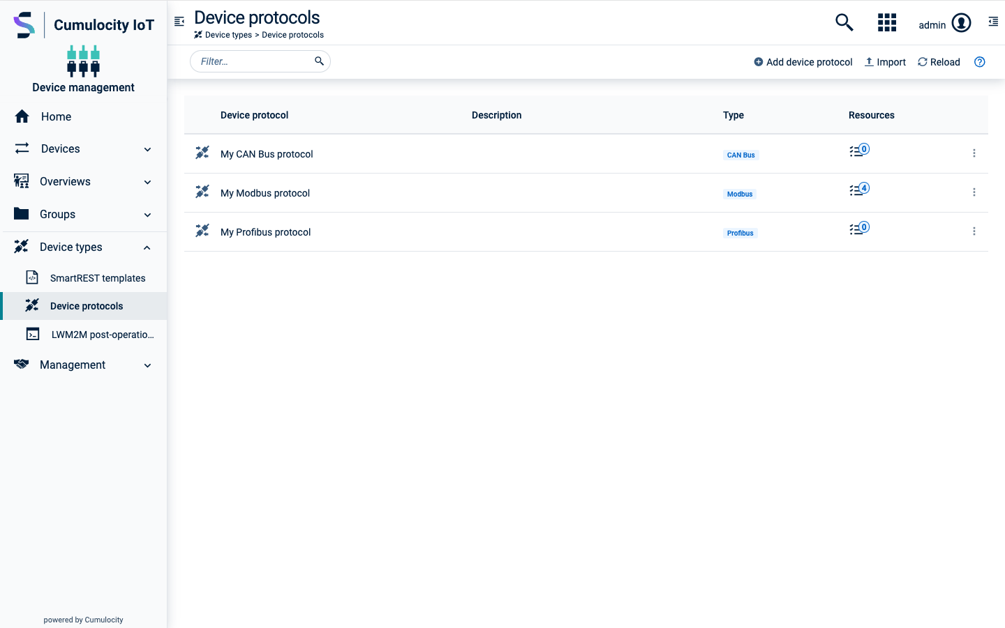
Next, you can configure the device protocol, following the descriptions for the respective protocol type below.
If you edit a device protocol that is currently in use, you may need to
* restart the terminals that use the device protocol,
* reconfigure dashboards and widgets that use the device protocol.
### Configuring Modbus device protocols {#configuring-modbus-device-protocols}
#### To add a coil definition (discrete outputs) {#to-add-a-coil-definition-discrete-outputs}
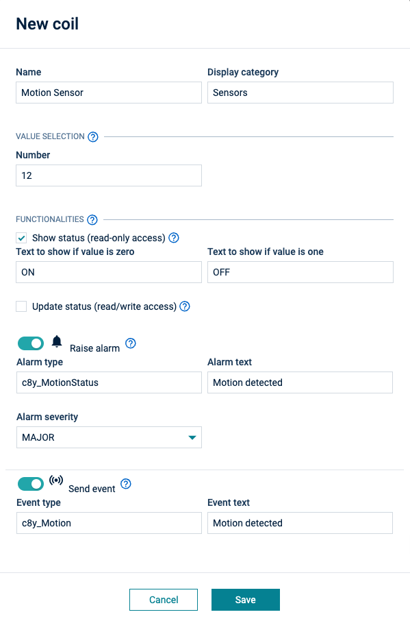
Click **Add Coil** in the **Coils (discrete output)** section, to add a coil definition.
1. Enter the name of the coil as being displayed in the user interface.
2. Optionally, enter the display category to structure your data in widgets.
3. In the **Value selection** section, enter the number of the coil in the Modbus device.
4. In the **Functionalities** section, you may select the following actions:
* **Show status** - To show the current value in the UI, for example, in the "Fieldbus device" widget. In this case, you can enter the text that the UI should show for unset and set coils.
* **Update status** - To enable to update the current value from the UI, for example, in the "Fieldbus device" widget.
* **Raise alarm** - To raise an alarm when the coil is set in the device. In this case, you can specify the type of the alarm that is raised, its text and its severity. Note that there can only be one alarm active of a particular type for a particular device.
* **Send event** - To send an event each time the value changes. If selected, you may specify the type of event and the text in the event.
5. Click **Save** to save your configuration.
#### To add a discrete inputs definition {#to-add-a-discrete-inputs-definition}
The same settings can be specified for discrete inputs. However, it is not possible to update the status of a discrete input.
#### To add a register definition {#to-add-a-register-definition}
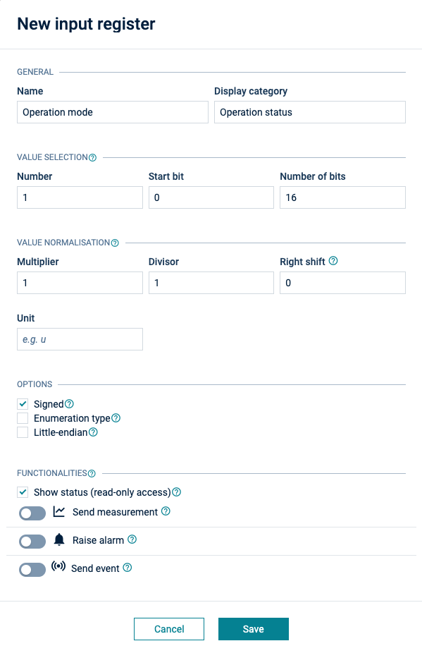
Click **Add holding register** under **Holding registers** or **Add input register** under **Input registers** to add a register definition.
1. In the **General** section, specify a name for the register and a display category to structure your data in widgets.
2. In the **Value selection** section, enter the number of the register in the Modbus device. You can indicate a subset of bits to be used from a register by providing a start bit and a number of bits. This allows you to split a physical Modbus register into a set of "logical registers". It is important to note that in Cumulocity registers are numbered as per the standard Modbus specification, that is they start from 1. This differs with some device manufacturers which count registers starting from 0.
3. In the **Normalization** section, specify how the raw value should be transformed before storing it in the platform. To scale the integer value read from the Modbus device, you can enter a **Multiplier**, a **Divisor** and a number of decimal places in the **Right Shift** field. The register value is first multiplied by the multiplier, then divided by the divisor and then shifted by the number of decimal places. Note, that the terminal may use integer arithmetic to calculate values sent to Cumulocity. For example, if you use a divisor of one and one decimal place, a value of 231 read from the terminal will be sent as 23.1 to Cumulocity. If you use a divisor of ten and no decimal places, the terminal may send 23 to Cumulocity (depending on its implementation). In the **Unit** field, indicate the unit of the data, for example, "C" for temperature values.
4. In the Options section, select the following options:
* **Signed** - If the register value should be interpreted as signed number.
* **Enumeration type** - If the register value should be interpreted as enumeration of discrete values. If **Enumeration type** is selected, you can click **Add value** to add mappings from a discrete value to a text to be shown for this value in the widget. Click **Remove value** to remove the mapping.
* **Little endian** - If the register value should be interpreted in little-endian format based on 8-bit values.
5. In the **Functionalities** section, you may select the following actions:
* **Show status** - To show the current value in the UI, for example, in the "Fieldbus device" widget.
* **Update status** - To enable to update the current value from the UI, for example, in the "Fieldbus device" widget. If **Update status** is selected, two additional fields **Minimum** and **Maximum** appear. Using these fields, you can constrain numerical values entered in the widget.
* **Send measurement** - To collect the values of the register regularly according to the transmit interval (see [above](https://cumulocity.com/docs/device-integration/cloud-fieldbus/#connecting-fieldbus)). In this case, add a measurement type and a series to be used. For each measurement type, a chart is created in the **Measurements** tab. For each series, a graph is created in the chart. The unit is used for labelling the measurement in the chart and in the "Fieldbus device" widget.
* **Raise alarm** - To raise an alarm when the register is not zero in the device measurement. In this case, you can specify the type of the alarm raised, its text and its severity. Note, that there can only be one alarm active of a particular type for a particular device.
* **Send event** - To send an event each time the value of the register changes. If selected, you may specify the type of event and the text in the event.
6. Click **Save** to save the register.
In the **Options** section, select the checkbox **Use server time** to create the time stamps for data on the server instead of on the terminal. If you must support buffering of data on the terminal, leave this checkbox clear.
Finally, click **Save** to save the device protocol.
### Configuring CAN bus device protocols {#configuring-can-bus-device-protocols}
CAN bus device protocols can be configured in a very similar way as Modbus device protocols. For more information, see [Configuring Modbus device protocols](https://cumulocity.com/docs/device-integration/cloud-fieldbus/#configuring-modbus-device-protocols) above. The differences are:
* Holding registers are used to describe the different pieces of data inside CAN messages.
* Enter the CAN message ID of the specific message the data should be extracted from. Use a hexadecimal number for the message ID.
* Conversion of values is extended by an offset parameter (for example, any positive or negative number). This is added or subtracted from the register value, depending on its sign. The offset calculation is done after applying multiplier and divisor, and before performing decimal shifting.
### Configuring Profibus device protocols {#configuring-profibus-device-protocols}
Profibus device protocols can be configured in the following way:
1. In the **Registers** section, click **Add register** to add one or more register definitions as described exemplarily for Modbus devices in [To add a register definition](https://cumulocity.com/docs/device-integration/cloud-fieldbus/#to-add-a-register-definition) above.
1. In the **Options** section, select the checkbox **Use server time** to create the time stamps for data on the server instead of on the terminal. If you must support buffering of data on the terminal, leave this checkbox clear.
1. Finally, click **Save** to save your settings.
### Configuring CANopen device protocols {#configuring-canopen-device-protocols}
CANopen device protocols can be configured in the following way:
In the **CANopen device type** field, specify the device type as a hex number.
In the **Variables** section, you determine the CANopen variables. Variables inside the "Object Dictionary"(OD) of the CANopen device can later be accessed by adding the variables to the device type definition.
Click **Add variable** to configure a new variable.
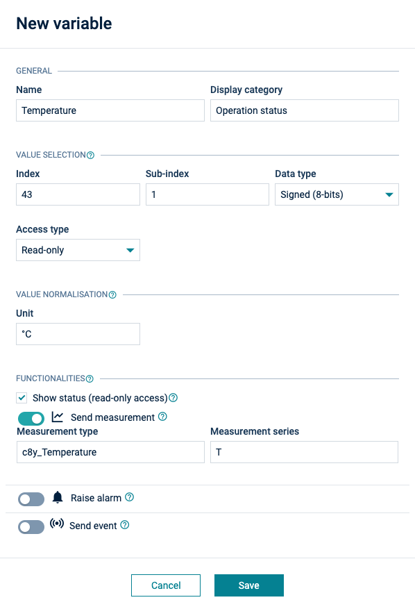
#### To configure a variable {#to-configure-a-variable}
1. In the **General** section, specify a name for the variable and a display category. Display categories are used to group variables into sections in the visualization.
2. In the **Value selection** section, specify from where the value should be extracted:
* **Index** - Index of the variable in the OD of the device.
* **Sub-index** - Sub-index of the variable in the OD of the device.
* **Data type** - Type of the variable (for example boolean, unsigned).
* **Access type** - Access type, for example, read-only, write-only.
3. Depending on the selected access type, the following functionalities may be specified:
* **Show status** - To enable to show the current value in the UI, for example, in the "Fieldbus device" widget.
* **Update status** - To enable to update the current value from the UI, for example, in the "Fieldbus device" widget. If selected, two additional fields **Minimum** and **Maximum** are displayed. Using these fields, you can constrain numerical values entered in the widget.
* **Send measurement** - To create a measurement whenever the value is changed. If selected, you may specify a **Measurement type** and **Measurement series**.
* **Raise alarm** - To raise an alarm if a given mask matches with the value of the variable ((value & mask) == mask). Additionally, you may specify the type of the alarm raised, its text and its severity.
* **Send event** - To send an event each time the value of the register changes. If selected, you may specify the type of event and the text in the event.
4. In the **Normalization** section, specify a unit to define how the raw value should be transformed before storing it in the platform.
5. Click **Save** to save the variable.
The variable will be listed in the **Variables** section of the device protocol. All variables are grouped by the given display category, that means, variables with the same category are grouped together.
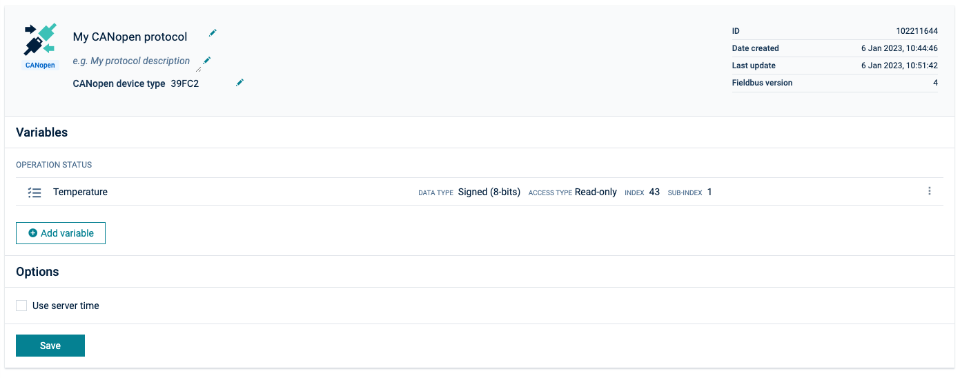
After completing your configuration, click **Save** to save the device protocol configuration.
#### Importing a CANopen device protocol {#importing-a-canopen-device-protocol}
See [Exporting and importing device protocols](https://cumulocity.com/docs/device-integration/cloud-fieldbus/#exporting-importing-protocols) for general information on how to import a device protocol.
After importing the EDS file, all variables defined in the file are listed in the **Variables** section of the CANopen device protocol.
The user can then enrich the imported variable configurations manually, for example by adding the missing display category.
#### Configuring CANopen device data {#configuring-canopen-device-data}
To configure CANopen device data navigate to the desired device and switch to the **CANopen** tab.
In the **CANopen communication** section, the following parameters can be configured:
- **Baud rate:** This field must match with the used baud rate in the CANopen network.
- **Polling rate:** The rate at which the agent sends requests to the CANopen devices.
- **Transmit rate:** The transfer rate, that is, the rate at which the terminal sends regular measurements to Cumulocity.
In the **CANopen** section, up to 127 CANopen devices can be added to the gateway as child devices by providing the following parameters:
- **Name:** The name of the device shown in the UI.
- **Device type:** The device type of the CANopen device. The user can select from a list of all CANopen device types which are stored in the device database.
- **Node ID:** The CANopen node ID of the device. It is used for addressing the device inside the CANopen network.
> **Info:**
> The device type and node ID must match with the real CANopen device, otherwise setting up the communication is not possible or wrong values will be transmitted.
## Exporting and importing device protocols
To manage device protocols more conveniently, you can export them to a file. The file can be re-imported to set up other Cumulocity accounts easily or to restore the protocols from a backup. The import functionality also supports importing ready-made device protocols provided by device manufacturers.
To export a device protocol, click the menu icon at the right of the respective row and click **Export**.
A file with the device protocol definition will be downloaded, named "<device type>.json".
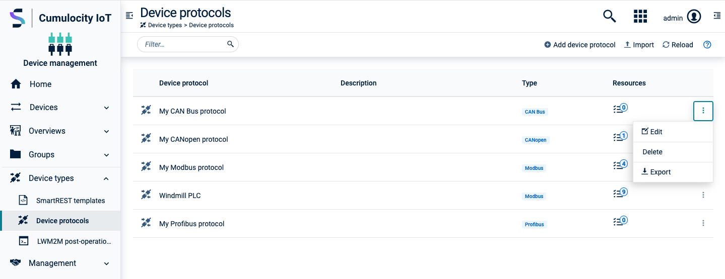
1. To import a device protocol, click **Import** in the top menu bar.
2. In the resulting dialog box, either select a pre-defined protocol or upload a file with a previously exported device protocol.
3. You may enter a new name for the device protocol.
4. Click **Import** to import the protocol.